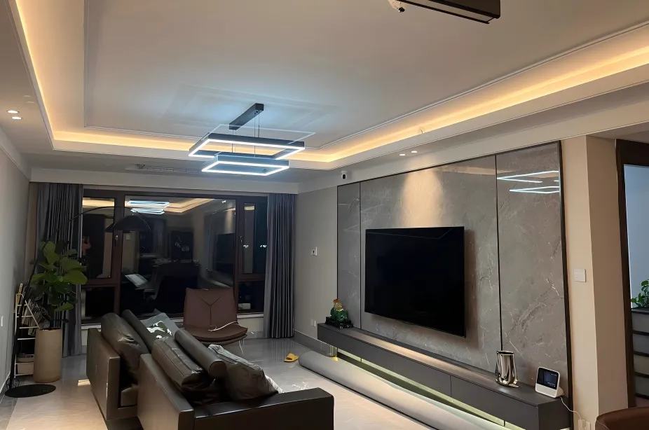
From across the kitchen, the cabinet lighting looks even. Move closer to the polished worktop and a row of white dots appears in its reflection. In a display cabinet, the same problem may be visible through glass or along the back panel. Hiding LED strip dots starts with identifying where those individual light points are being seen.
What Creates a Smoother Line of Light?
Match the LED spacing, internal mixing distance and cover as one optical assembly. Then position the fitting so its light reaches the required surface without exposing an unwanted source or reflection. A diffuser can help blend separate LEDs, but the finished result also depends on the profile geometry, cabinet materials and viewing position.
First, Locate the Dots
Visible LED dots, often called spotting or hotspots, can appear in several places. Check the cabinet from the position where people actually use it before changing the lighting components.
| What You See | What to Investigate | Useful Sample Comparison |
|---|---|---|
| Separate LEDs on the light's face | LED pitch, cover diffusion and the internal distance available for light blending. | Compare approved strip-and-cover assemblies at the same viewing distance. |
| Dots reflected in stone, glass or a mirror | The source pattern and the reflection path between the fitting, surface and viewer. | Compare mounting positions or optical designs using the actual reflective finish. |
| Alternating bright and dark patches on a panel | Source-to-panel distance, LED spacing and light distribution. | Compare the pattern at the proposed offset and an alternative permitted position. |
| One dark break at a cabinet joint | Lighted length, end caps, connectors and the gap between fittings. | Test two finished sections with their actual ends and connecting parts. |
On smaller screens, scroll the table horizontally. Each pattern calls for a different comparison.
Keep These Three Dimensions Separate
A deeper cabinet groove, a denser LED strip and a larger offset from a wall change different parts of the installation. Use the fitting's cross-section and the furniture drawing to identify the dimension you need to change.
P / LED PITCH
Between the LEDs
The center-to-center spacing of individual emitters. Smaller pitch gives adjacent light sources less distance to bridge.
H / MIXING GAP
Inside the Fitting
The distance from the LED's emitting face to the inside of the cover. The outside height of a profile does not establish this gap.
D / SURFACE DISTANCE
Outside the Fitting
The distance from the light opening to the shelf, worktop or back panel. This affects how the light pattern spreads across that surface.
For uniformly spaced single-row LEDs, nominal pitch in millimeters is 1000 divided by the LEDs per meter. As arithmetic examples, 60 LEDs/m gives about 16.7 mm pitch; 120 LEDs/m gives about 8.3 mm. These examples explain spacing and are not specifications for the ARTCILUX models below.
Waveform Lighting's explanation of LED density describes how spacing and distance affect visible light points. Review the actual emitter layout alongside the cover and internal geometry.
There is no universal profile depth that hides every LED strip. Compare the complete optical assembly. Also confirm panel thickness, groove dimensions, fixing parts and cable clearance before choosing a deeper recessed housing.
Choose the Cover and Optical Structure Together
A plain clear cover offers little diffusion. Frosted or milky covers scatter light, with the result depending on their optical properties and the assembly behind them. Compare the usable light output with the specified cover fitted as well as the smoothness of the visible line.
Waveform Lighting's discussion of channels and diffusers explains how diffusion changes direct and reflected light. A cover marked PC or PMMA identifies its material; it does not, by itself, describe the finished optical effect.
COVER EXAMPLE
A220D: Milky White PC Cover
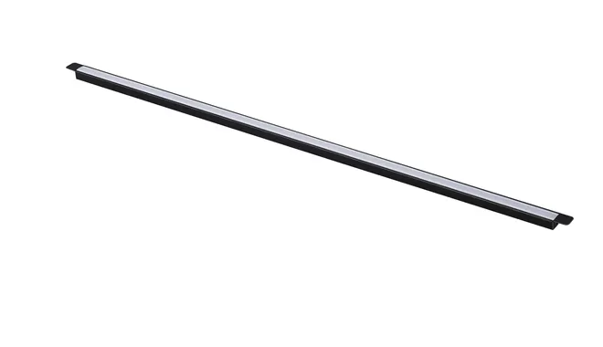
ARTCILUX A220D is a recessed strip light with clip installation and a milky white PC light-guiding cover. Its cover is part of the fitting's optical design.
When reviewing a cabinet sample, inspect the lit face and its reflection on the proposed finish. Check useful illumination with the cover in place.
OPTICAL DESIGN EXAMPLE
A220EA: Oblique Reflection Design
ARTCILUX A220EA uses an oblique reflection principle, with clip installation and customizable length. This brings the light's direction into the selection alongside the visible cover.
Compare the proposed orientation from normal viewing positions. Confirm both surface coverage and the appearance of reflections before machining the panel.
Both models list 12V, 7.5W/m and SMD2835 LEDs, with Ra above 90 and 3000K, 4000K or 6000K options. The SMD2835 designation does not specify the number of LEDs per meter or their installed pitch. Request the complete drawing and a lit sample for the selected configuration.
Also distinguish bare tape from an integrated flexible light. ARTCILUX's flexible cabinet strip lighting range describes silicone co-extrusion. For an integrated product, evaluate its supplied optical structure and approved mounting arrangement.
Place the Light for the Surface and the Viewer
Polished Kitchen Worktops
A cabinet lip may hide the strip from direct view while leaving its reflection visible on the worktop. Test the proposed position with the actual stone or glossy finish. Compare offsets or fitting orientations within the approved mounting options, checking from standing and seated positions.
Keep the usable work area illuminated during that comparison. Moving the source to conceal a reflection can also change shadows beneath the cabinet.
Wardrobes and Deep Shelves
Check the view with doors open and shelves loaded. A line that looks smooth in an empty cabinet may leave dark areas once clothing or storage boxes are in place. Review front-edge or vertical positions against shelf obstructions, door movement and the required illuminated area.
Glass Shelves and Display Cabinets
Inspect through the glass and from the sides, particularly where mirror backs or polished display objects introduce another reflection. Position the fitting so it supports the intended display view. Check the line, its reflected image and the objects together.
Approve a Complete Cabinet Sample
Use the selected light, cover, end parts, mounting section and furniture finish. Keep CCT and brightness settings consistent when comparing candidates. Agree on the required appearance from defined viewing positions.
| Check | Sample Setup | Acceptance Question |
|---|---|---|
| Visible light face | Cover fitted; normal standing, seated or display viewing positions. | Does the line meet the agreed smoothness and visibility requirement? |
| Reflected image | Actual worktop, glass, mirror or approved material sample at its installed position. | Are reflected dots or bright lines acceptable from the intended viewing positions? |
| Useful illumination | Full cabinet depth with representative shelf contents or work objects. | Does the selected assembly provide the required coverage without unwanted bands or shadows? |
| Ends and joints | Finished sections with end caps, cable feeds and planned cabinet joints. | Do the illuminated ends and section gaps match the approved design? |
Record the approved model, cover, CCT, brightness setting and mounting drawing. Photographs taken from marked positions with consistent exposure can support the record; inspect the light by eye as well.
LED Strip Dots: Common Questions
Can I add a diffuser to an existing cabinet strip light?
If the product is designed for a separate or replaceable cover, check the matching component and available mixing gap. For a finished fitting or silicone-integrated light, use the manufacturer's approved assembly. A generic cover may change fit, light distribution and usable output.
What profile depth guarantees dot-free LED lighting?
Depth alone cannot provide that guarantee. LED pitch, the actual LED-to-cover gap, cover properties and viewing conditions all matter. Validate the proposed assembly with the selected strip and the real cabinet finish.
Does a COB strip remove the need for a profile or cover?
COB designs can create a more continuous emitting line, as illustrated in Armacost Lighting's explanation of COB tape light. Mounting, protection and thermal requirements still depend on the selected product. A continuous source may also remain visible as a bright line in a polished surface.
Will dimming hide the LED dots?
Dimming can make a source less conspicuous, but it does not change LED spacing or the optical geometry. Check the pattern at the brightness levels the cabinet needs. Resolve blending and placement alongside the required illumination.
Review the Light Effect Before Cutting the Groove
Send ARTCILUX the cabinet section drawing, panel thickness, proposed mounting position, surface finish and preferred CCT. If dots or reflections are already visible, include photos from the normal viewing position.
We can review options from the cabinet strip light range and identify the fitting details to confirm with a project sample.
Request a Cabinet Strip Lighting ReviewEmail: sales@artcilux.com