Successful cabinet lighting installation starts before the cabinets reach the jobsite. The lighting type, profile position, cable route, LED driver capacity, sensor location and maintenance access should all be confirmed during cabinet design. For most integrated systems, the installation sequence is straightforward: plan the lighting zones, select compatible 12V or 24V fixtures, calculate the total load, position the driver and sensors, route the low-voltage wiring, mount the profiles, connect the system and test every control function. This guide explains how cabinet makers, furniture manufacturers, contractors and lighting designers can complete those steps while reducing visible wiring, dark areas, voltage drop, false sensor triggering and future maintenance problems.
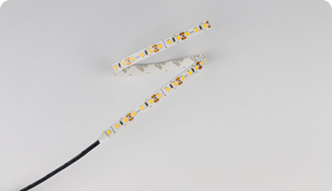
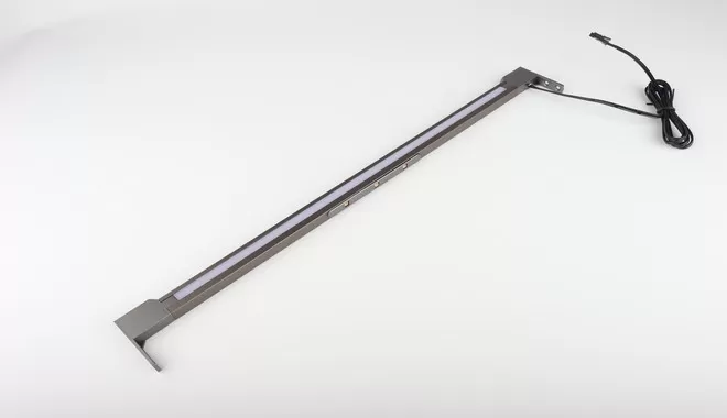
Cabinet lighting should be treated as a complete system rather than a collection of unrelated parts. A typical system includes LED lights, aluminum profiles, an LED driver, sensor switches, controllers, cables, connectors and distribution accessories. Specifying these components together helps ensure that the voltage, wattage, control protocol and connectors are compatible.
What Is Included in a Cabinet Lighting System?
A complete cabinet lighting installation normally contains four functional layers: the light source, the mounting structure, the power system and the control system.
| System Component | Main Function | Important Selection Factors |
|---|---|---|
| LED strip, linear light, spotlight or light panel | Provides task, accent or display lighting | Voltage, wattage, brightness, color temperature, CRI and beam distribution |
| Aluminum profile and diffuser | Supports the light source, manages heat and creates a finished appearance | Recessed or surface-mounted design, profile depth, diffuser type and cutout dimensions |
| LED driver or power supply | Converts the mains input into the low-voltage output required by the lighting | Input voltage, 12V or 24V output, rated wattage, dimensions, protection and dimming compatibility |
| Sensor switch or controller | Turns the lights on, off or dims them | Door, hand-wave, PIR or touch control; wired or wireless communication; sensing distance |
| Cables, connectors and splitters | Distribute power and control signals between components | Current rating, polarity, cable length, connector type and installation space |
Artcilux provides integrated cabinet LED lighting, cabinet sensor switches, cabinet LED driver power supplies and smart cabinet lighting controls for furniture and millwork projects.
Plan the Cabinet Lighting Before Production
The most common cabinet lighting problems are often caused by late planning. When lighting is added after cabinet production, installers may have nowhere to hide the driver, no channel for the cable and no suitable position for the sensor. The light may also produce glare because the profile position was not considered during the cabinet design stage.
Before cutting panels or producing cabinets, confirm the following information:
Which cabinets, shelves, drawers or work surfaces require lighting?
Is the light intended for task lighting, accent lighting, display lighting or navigation?
Will the system use 12V DC or 24V DC?
Will the light be recessed, surface-mounted or integrated into a shelf?
Where will the LED driver be installed and accessed?
Where will cables pass between cabinets and panels?
Which lights should operate together as one zone?
Will the system use a door sensor, hand-wave sensor, touch dimmer, PIR sensor or smart controller?
Are there wet, humid or high-temperature areas that require additional protection?
For furniture factories, these decisions should be included in production drawings, drilling drawings, routing drawings and the bill of materials. Each cable outlet, profile groove, sensor hole and driver compartment should have a defined position and dimension.
Choose the Right Cabinet Light for Each Position
Different cabinet areas require different light distributions. Selecting a fixture only by appearance can lead to visible LED dots, glare, shadows or uneven illumination.
| Installation Area | Recommended Lighting Type | Placement Guidance |
|---|---|---|
| Under kitchen wall cabinets | Linear light, LED strip in profile or slim light panel | Position toward the front of the cabinet to illuminate the worktop and reduce shadows |
| Inside wardrobes | Vertical linear light, shelf light or hanging-rail light | Keep the light clear of clothing and install where the door will not block the beam |
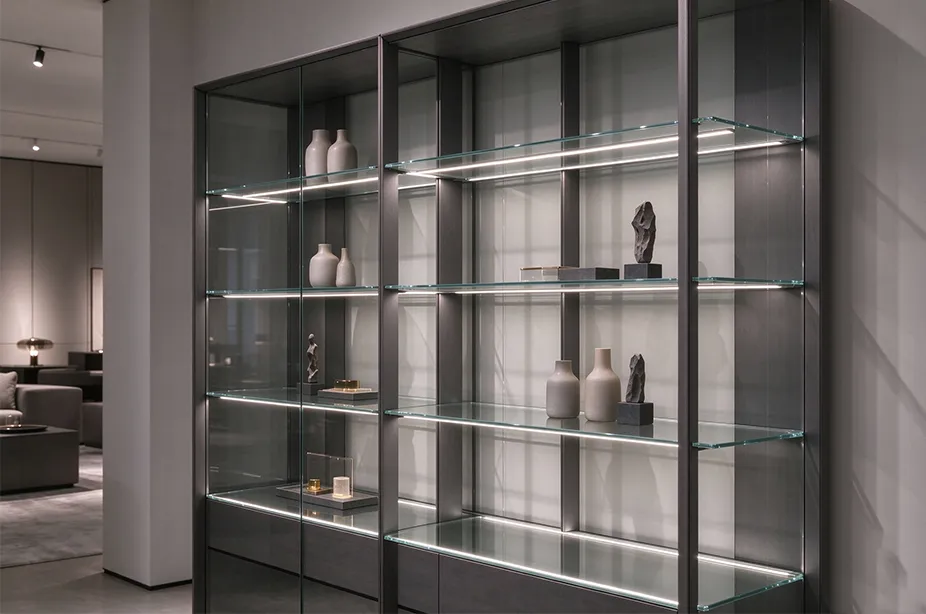
| Display cabinets | Mini spotlight, shelf light or concealed linear light | Aim the light toward the displayed object while keeping the LED source outside the main viewing angle |
| Drawers | Compact linear light or flexible strip | Mount near the front or upper edge and protect the cable from moving drawer parts |
| Open shelves | Recessed linear profile | Install near the front for downward illumination or near the rear for a wall-washing effect |
| Bathroom vanity cabinets | Protected linear light or mirror lighting | Select a product suitable for the installation environment and keep electrical components away from water exposure |
For kitchen projects, explore Artcilux kitchen cabinet lighting solutions. For wardrobes and dressing rooms, the cloakroom cabinet lighting page provides additional application options.
12V vs 24V Cabinet Lighting: Which Voltage Should You Use?
Both 12V and 24V constant-voltage systems are widely used in cabinet lighting. The correct voltage depends on the selected lights, cable length, total load and project design.
When a 12V System May Be Suitable
A 12V cabinet lighting system can work well for compact furniture, short lighting runs and products already designed around 12V components. It may also be appropriate when an existing furniture lighting platform uses standardized 12V drivers, sensors and connectors.
When a 24V System May Be Better
At the same wattage, a 24V system draws less current than a 12V system. Lower current can help reduce voltage loss in long cable runs and may make 24V more suitable for larger kitchens, long wardrobes, multiple shelves or projects with several connected lighting zones.
Do not mix a 12V light with a 24V driver or a 24V light with a 12V driver. The output voltage of the driver must match the rated input voltage of every downstream fixture, sensor and controller.
How to Calculate the Correct LED Driver Wattage
An undersized driver may overload, shut down, flicker or operate at an excessive temperature. An unnecessarily oversized driver may increase cost and occupy more installation space. The driver should be selected according to the real connected load and the manufacturer's operating requirements.
Step 1: Calculate the Lighting Load
For LED strip lighting, multiply the wattage per meter by the installed length:
Total strip load = watts per meter × total installed meters
For individual cabinet lights, multiply the wattage of each light by the quantity:
Total fixture load = wattage per fixture × number of fixtures
If a system combines several products, add all loads together.
Step 2: Add an Appropriate Power Reserve
Many cabinet lighting projects include additional driver capacity rather than operating continuously at the maximum rating. The exact reserve should follow the power supply datasheet and the project conditions. A design reserve of approximately 15% to 25% is often used as a practical starting point, but it is not a universal requirement.
Driver Calculation Example
A kitchen project uses four linear lights rated at 6W each:
Connected lighting load: 4 × 6W = 24W
Load with a 20% design reserve: 24W × 1.20 = 28.8W
Possible driver selection: a compatible driver rated above 28.8W
The final driver must also match the required output voltage, input voltage, control method, ambient conditions and applicable certification requirements. Artcilux offers ultra-thin smart driver power supplies designed for furniture lighting integration.
Where Should the LED Driver Be Installed?
The LED driver should be concealed but still accessible. Completely sealing the driver behind a finished panel can make inspection and replacement difficult. It may also restrict ventilation if the installation does not follow the product instructions.
Common driver locations include:
Above a wall cabinet
Inside a dedicated service compartment
Behind a removable cabinet panel
Inside a ventilated technical cabinet
Above a wardrobe or display unit
Near an accessible electrical outlet
Keep the driver away from sinks, plumbing, steam, excessive heat and areas where stored objects may damage the cables. Do not cover ventilation openings or install a power supply in a smaller enclosure than permitted by its instructions.
Connections to mains electricity must comply with local electrical codes. Hardwired installations should be completed by a qualified electrician. Always disconnect the power before wiring, inspection or maintenance.
How to Wire Cabinet LED Lights
A typical low-voltage cabinet lighting circuit follows this sequence:
Mains input → LED driver → controller or sensor → splitter → cabinet lights
The exact sequence can vary. Some smart power supplies integrate control functions, while some sensors are installed between the driver and the lighting load. Always follow the wiring diagram for the selected products.
Parallel Wiring for Multiple Cabinet Lights
Many constant-voltage cabinet lighting systems connect multiple lights in parallel. In a parallel circuit, each branch receives the rated system voltage. This makes it easier to create several lighting branches from one compatible driver and distribution box.
Do not assume that every lighting product can be connected in parallel. Confirm the permitted wiring method, maximum number of fixtures, cable length and connector capacity in the product documentation.
Maintain the Correct Polarity
DC cabinet lights generally have positive and negative conductors. Reversed polarity can prevent the light from operating and may damage components that do not include reverse-polarity protection.
Use standardized cables and connectors throughout the system. During installation, label each branch by cabinet number or lighting zone so that future troubleshooting does not require opening every cabinet.
Plan Lighting Zones
Not every cabinet light needs to operate at the same time. A large project can be divided into zones such as:
Kitchen worktop lighting
Inside-cabinet lighting
Display shelf lighting
Toe-kick or navigation lighting
Wardrobe lighting
Decorative ambient lighting
Separate zones provide more flexible control and can simplify maintenance. Confirm whether the project requires individual sensors, group control, synchronized dimming or smart-home integration.
How to Reduce Voltage Drop
Voltage drop occurs when the voltage reaching the light is lower than the voltage at the power supply. In cabinet lighting, excessive voltage drop can cause the lights at the end of a long run to appear dimmer or display a different color.
Voltage drop is influenced by:
Total cable length
Cable conductor size
Current carried by the cable
Number and quality of connectors
Total lighting load
System voltage
Many low-voltage lighting guidelines use approximately 3% or less as a design target, although the acceptable value should be confirmed for the selected lighting system and local requirements.
To reduce voltage drop:
Use the cable size recommended by the manufacturer.
Keep the driver reasonably close to the connected lights.
Avoid sending the entire project load through one long, small cable.
Divide large installations into multiple branches or zones.
Use power injection or additional drivers where the system design permits it.
Consider 24V equipment for longer runs when compatible products are available.
Minimize unnecessary connectors and check every termination.
Select and Position the Cabinet Sensor Switch
The sensor must be selected according to how the cabinet will be used. A sensor that works well in a wardrobe may not be the best choice for a kitchen worktop or display cabinet.
| Sensor Type | How It Works | Typical Applications | Placement Considerations |
|---|---|---|---|
| Door sensor | Responds when a cabinet or wardrobe door opens and closes | Wardrobes, cabinets, drawers and storage units | The door must reliably enter the sensing range when closed |
| Hand-wave sensor | Responds when a hand moves near the sensor | Kitchen cabinets, worktops and hygienic touch-free controls | Keep the detection area away from doors or objects that could cause false triggering |
| Touch sensor | Responds to physical touch and may support dimming | Display cabinets, desks, shelves and decorative furniture | The touch point should be easy to reach and clearly defined |
| PIR sensor | Detects human movement within the sensing area | Walk-in wardrobes, closets and automatic navigation lighting | Avoid obstructions and confirm the detection direction, range and delay time |
Artcilux's LED sensor switch range includes door, hand-movement, touch and PIR options. Wired models can provide direct integration with compatible cabinet lighting systems, while wireless sensor switches can simplify projects where routing control cables is difficult.
Door Sensor Placement
Install a door sensor where the closed door enters its specified detection area. Test the real door gap, hinge movement and final alignment before drilling the sensor hole. A sensor positioned correctly on an unfinished cabinet may stop working after door adjustment, edge banding or hardware installation changes the gap.
Hand-Wave Sensor Placement
Place a hand-wave sensor where users can activate it naturally without reaching behind doors or equipment. Avoid pointing it toward moving cabinet doors, reflective objects or nearby work areas that may create unintended activation.
PIR Sensor Placement
A PIR sensor needs a clear view of the expected movement area. Do not hide it behind a solid cabinet frame unless the product is specifically designed for concealed sensing. In a walk-in wardrobe, position the sensor so that a person entering the space crosses the detection area.
Recessed vs Surface-Mounted LED Profile Placement
The aluminum profile affects appearance, light distribution, installation speed and heat management. Profile placement should therefore be shown on the cabinet drawing rather than decided at the jobsite.
Recessed LED Profiles
Recessed profiles create a more integrated appearance because the profile sits inside a machined groove. They are commonly used in premium shelves, wardrobes, display cabinets and custom millwork.
Before machining the groove, confirm:
Profile width and depth
Required cutout tolerance
Diffuser installation direction
Cable outlet location
End-cap clearance
Minimum panel thickness
Whether the profile must remain removable
Surface-Mounted LED Profiles
Surface-mounted profiles require less panel machining and can be suitable for retrofit projects or furniture designs with limited panel thickness. However, the profile, cable and mounting clips may be more visible.
Use mechanical clips, screws or the approved mounting method for the product. Adhesive alone may not be suitable for every material, temperature or long-term application.
Front, Center or Rear Placement?
Under a kitchen wall cabinet, positioning the light closer to the front edge generally directs more light toward the worktop and reduces shadows created by the user's body. A rear-mounted light may emphasize the backsplash but provide less uniform task lighting at the front of the work surface.
Inside a display cabinet, front placement can illuminate the face of an object, while rear placement can create a wall-washing or silhouette effect. The best position should be confirmed through a sample cabinet or lighting mock-up.
Step-by-Step Cabinet Lighting Installation Process
Review the drawings. Confirm every lighting zone, profile groove, driver position, sensor position and cable outlet.
Verify component compatibility. Check voltage, wattage, connector type, sensor load rating and control method.
Disconnect mains power. Do not work on energized electrical circuits.
Prepare the cabinet. Machine profile grooves and drill cable and sensor openings according to approved dimensions.
Route the low-voltage cables. Protect cables from sharp edges, hinges, drawer runners and moving doors.
Install the LED driver. Keep it accessible and follow ventilation and mounting requirements.
Install the profiles and lights. Ensure profiles are straight, secure and free from debris before fitting diffusers.
Install sensors and controllers. Confirm the sensing direction and required clearance.
Connect each lighting branch. Maintain correct voltage and polarity and do not exceed connector or driver ratings.
Test before closing panels. Check every light, zone, sensor and dimming function while components remain accessible.
Complete final commissioning. Inspect brightness consistency, heat, cable concealment, sensor response and maintenance access.
Cabinet Lighting Testing and Commissioning Checklist
All lights operate without flicker.
Brightness remains consistent across long runs.
Color temperature matches between fixtures.
No individual LED points are visible where a continuous light effect is required.
The driver does not exceed its rated load.
The driver and controllers remain accessible.
Door sensors respond to every door opening and closing cycle.
Hand-wave sensors do not trigger from normal cabinet movement.
PIR sensors cover the intended detection area.
Dimmers operate smoothly throughout the required range.
Cables are protected from hinges, runners and sharp panel edges.
Profiles, diffusers and end caps are secure.
All mains connections meet local electrical requirements.
Common Cabinet Lighting Installation Problems
| Problem | Possible Cause | What to Check |
|---|---|---|
| Lights do not turn on | No mains input, reversed polarity, loose connector or incompatible voltage | Input power, driver output, polarity, plugs and product voltage |
| Lights flicker | Driver overload, incompatible dimmer, poor connection or unstable control signal | Total load, dimming compatibility, cable terminals and controller settings |
| End of strip appears dim | Excessive voltage drop or a run longer than permitted | Cable length, conductor size, strip length and power injection options |
| Door sensor stays on | Door is outside the sensing range or sensor alignment is incorrect | Door gap, sensor direction, mounting distance and reflective surfaces |
| PIR sensor triggers incorrectly | Poor position, obstruction or movement outside the intended area | Detection angle, installation height, cabinet frame and nearby movement |
| Visible LED dots | Shallow profile, insufficient diffuser depth or low LED density | Profile depth, diffuser type, LED spacing and viewing distance |
| Driver becomes too hot | Overload, restricted ventilation or unsuitable installation environment | Connected load, ambient temperature, ventilation and driver instructions |
Cabinet Lighting Installation FAQ
Should cabinet LED lights be wired in series or parallel?
Many constant-voltage 12V and 24V cabinet lights are connected in parallel so that each branch receives the rated voltage. However, the correct wiring method depends on the product. Always follow the manufacturer's wiring diagram and maximum-load requirements.
How much extra capacity should an LED driver have?
The required reserve depends on the driver specifications, ambient temperature and application. A margin of approximately 15% to 25% is often used as a starting point, but the final selection must follow the driver datasheet and the actual project conditions.
Where should an under-cabinet light be positioned?
For kitchen task lighting, the fixture is commonly positioned toward the front of the wall cabinet so that more light reaches the worktop and fewer shadows are created. The final position should be tested because cabinet depth, backsplash material and beam angle affect the result.
Can one sensor control multiple cabinet lights?
Yes, one compatible sensor may control several cabinet lights through a driver, controller or splitter, provided the combined load does not exceed the rated capacity of the sensor and other components. Check the complete system ratings before installation.
Can a cabinet LED driver be completely hidden?
The driver can be concealed, but it should remain accessible for inspection and replacement. Its installation must also provide the ventilation, clearance and environmental protection required by the manufacturer.
Do I need an electrician to install cabinet lighting?
Plug-in low-voltage systems may be assembled according to the manufacturer's instructions, but mains-voltage and hardwired connections should be completed by a qualified electrician in accordance with local electrical codes.
Plan an Integrated Cabinet Lighting System with Artcilux
A reliable cabinet lighting installation depends on coordination between cabinet design, electrical engineering and component selection. Lights, drivers, sensors, controllers, cables and profiles should be reviewed as one system before furniture production begins.
Artcilux supports cabinet makers, furniture brands, lighting companies, designers and project contractors with integrated lighting solutions for kitchens, wardrobes, display cabinets, shelves, bathrooms and whole-house furniture systems. Customization options can include fixture dimensions, color temperature, profile structure, cable length, connectors, control methods, packaging and project documentation.
To receive a product recommendation, prepare the cabinet drawing, lighting dimensions, required voltage, total quantity, sensor type, target market and certification requirements. Contact Artcilux for a cabinet lighting system evaluation and quotation.