An integrated cabinet lighting system combines LED lights, a compatible power supply, controls and connections into one coordinated solution for furniture. It also accounts for how the lights are mounted, where the cables run and how components can be accessed for service.
The aim is to make the lighting fit the cabinet and behave as intended: a wardrobe bay lights when its door opens, a kitchen worktop receives useful task lighting, or a display shelf shows its contents without an exposed bright light source.
For cabinet makers and furniture manufacturers, the decisions extend beyond choosing a light bar. The fixture length must fit the furniture, the driver must suit the electrical load, and the sensor or controller must operate the intended lights. Planning these parts together gives the assembly team a clear specification to follow across samples and repeat orders.
What does an integrated cabinet lighting system include?
A complete system covers five practical functions. They do not always require five separate products: a driver may include a sensor input, while a receiver may handle both switching and dimming. Select the combination that matches the furniture and the required control behavior.
| System part | What it does | What to confirm |
|---|
| LED lights | Illuminate worktops, shelves, wardrobe interiors or displayed objects. | Fixture dimensions, mounting method, rated voltage, power, light output and color temperature. |
| LED driver / power supply | Convert the specified mains supply into the electrical output required by the lights. | Mains input range, output type and voltage, total load, output-port limits and installation conditions. |
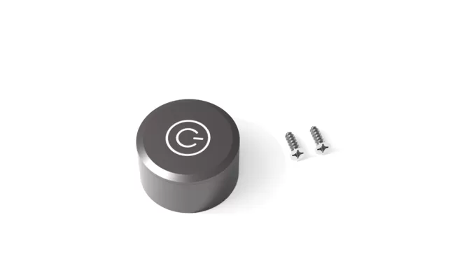
| Sensors, switches and controllers | Provide door, hand-wave, touch, motion or manual control; supported models can also adjust brightness or color temperature. | The intended function, sensor position, control interface and which lights each control operates. |
| Cables and connectors | Connect the lights, driver and any separate control components. | Cable length, conductor size, polarity, connector ratings and pin assignments. |
| Mounting and service provisions | Secure the lights, protect cable routes and allow component access. | Recess or fixing dimensions, profiles and diffusers where required, driver access and replacement procedure. |
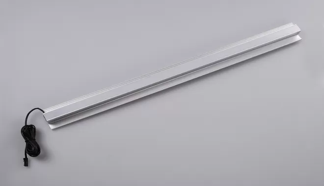
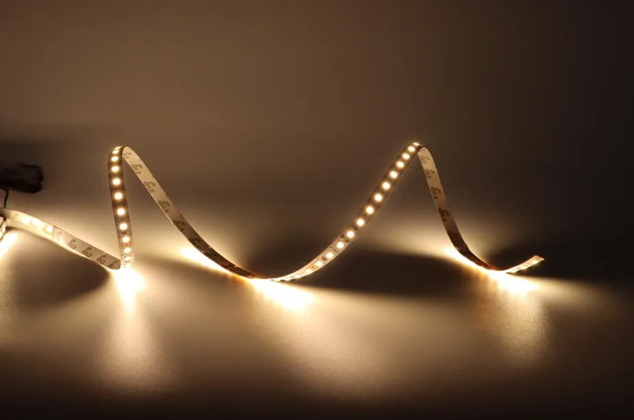
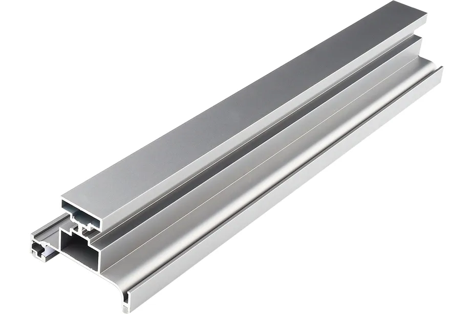
For example, a wired door-controlled wardrobe may need no wireless receiver. A tunable-white display requires a fixture and control arrangement that support color-temperature adjustment. An aluminum profile is useful where the selected strip and mounting design require it; a finished light bar may already include its own housing and diffuser.

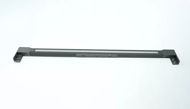
A recessed light bar is the visible lighting component. Its power supply, controls and connections still need to be matched to the furniture design.
How do the lights, driver and controls work together?
Think about two related functions: supplying power and receiving a command. A wireless sender can request a change in brightness, but it does not supply electrical power to the lights.
| Function | What happens | What this means for the system |
|---|
| Power supply | The mains supply feeds the LED driver. The driver supplies the lights through compatible connections and any required load-side controller. | The driver, lights, cables and controller must have compatible voltage, current and output requirements. |
| Lighting control | A sensor, switch or wireless sender requests switching, dimming or color-temperature adjustment. | The receiving interface must recognize the command and support the requested function. |
In a door-controlled wardrobe, opening a door triggers the selected sensor. The compatible driver or controller then switches the assigned lights according to the specified control arrangement. Closing the door switches them off if that is the configured behavior.
The exact connections depend on the selected models. Some sensors use a dedicated control port on the driver; others operate within a low-voltage circuit. Follow the product connection instructions. For connection details, see the cabinet lighting wiring guide.
A matching plug or frequency does not establish compatibility. Similar-looking connectors can have different pin assignments. Two wireless products can both use 2.4GHz while using different protocols. Confirm the actual product combination before approving it for production.
How the system changes for different cabinet applications
The same component categories can serve different furniture designs. The lighting task and the way people use the cabinet determine the fixture position and control requirements.
| Application | Lighting purpose | System priorities |
|---|
| Kitchen under-cabinet lighting | Illuminate the worktop and preparation area. | Position the fixture to reduce shadows and direct glare; provide convenient manual, touch or hand-wave control as required. |
| Wardrobe and storage interiors | Make clothes and stored items visible when the cabinet is accessed. | Coordinate sensor placement with door movement; specify whether compartments operate independently or together. |
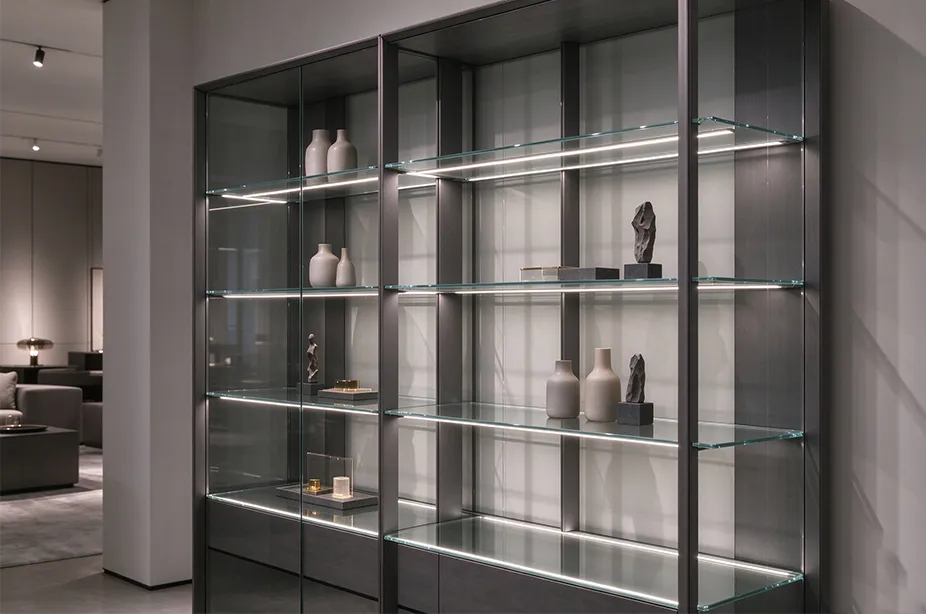
| Shelves and display cabinets | Illuminate objects and reveal the appearance of materials. | Select fixture positions, diffusers and light appearance using a sample; confirm dimming or color-temperature control where required. |

In a kitchen, the lighting position should support the work surface. The final cabinet design also needs a practical location for the driver and cable connections.
Example: planning a two-bay wardrobe lighting system
Consider a wardrobe with two separately used compartments. The requirement is simple: opening the left door should illuminate the left bay, while the right bay responds to its own door. This is a planning example, rather than a customer installation claim.
Define the control behavior. Record what happens when either door opens, when both doors are open and when they close.
Select the lights for each bay. Match their lengths and mounting positions to the furniture drawings, and check that the stored items are illuminated without an exposed bright source.
Match the power supply. Use the fixture-rated voltage and assess the combined connected load. Check individual port and controller limits as well as the driver total.
Confirm independent control. The chosen sensors and driver or controller arrangement must support the required separation. Several power outlets alone do not establish independent lighting zones.
Plan assembly and maintenance. Specify sensor positions, cable lengths, protected routes and an accessible driver location before production.
If the brief changes so that either door turns on both bays, the fixture choice may stay similar while the controls and wiring change. Describe the required behavior explicitly in the system specification.
For electrical sizing, use the 12V vs 24V cabinet LED driver guide. If the project needs a fixed wireless user control, read how to choose a 2.4GHz wall panel remote.
What should cabinet makers specify before sampling?
Combine the electrical bill of materials with the furniture drawings. A useful specification allows the sample assembler and the production team to build and check the same lighting arrangement.
| Requirement | What to record |
|---|
| Furniture and mounting | Cabinet dimensions and materials, light positions, recess or fixing details, and available space for the driver. |
| Light appearance | Fixture lengths, color temperature, color-rendering requirement, diffuser and the agreed sample appearance. |
| Electrical configuration | Exact fixture, driver and controller models; target supply market; voltage; connected load; cable and connector details. |
| Control behavior | Which sensor or switch operates which lights; dimming or color-temperature functions; zone mapping and required behavior after a power cycle. |
| Assembly and service | Cable routes and lengths, component labels, mounting drawings, access points and replacement method. |
| Sample acceptance | Physical fit, illumination, door or motion response, wireless operation where used, dimming behavior and restart behavior. |
Test the complete furniture sample. A bench test does not reproduce every cable distance, door alignment, sensor position or metal enclosure in the finished cabinet. Record approved changes against the bill of materials before repeating the design in production.
For additional technical background on LED driver types and dimming compatibility, see the MEAN WELL technical FAQ. Apply the specifications of the actual driver and lights selected for your project.
Frequently asked questions about integrated cabinet lighting
Is an integrated cabinet lighting system the same as an integrated LED fixture?
An integrated LED fixture usually means a light fitting with an LED module built into it. An integrated cabinet lighting system describes the coordinated lights, power, controls and installation provisions for the furniture. Check which meaning the product specification uses.
Does every cabinet lighting system need a separate controller?
No. The required switching or dimming function may be built into a driver or another component. A separate controller or receiver is needed when the selected interfaces and requested functions require one.
Can wired sensors and a wireless remote work in the same system?
They can when the system is designed to support both. Confirm the permitted connections and what happens when a door sensor and a manual control request different lighting states. Wireless lighting control still requires power wiring to the lights.
Should the system use 12V or 24V?
Match the fixture-rated voltage first. Then assess connected power, cable distances, port limits and controls. A 24V supply cannot directly replace a 12V supply for lights that require 12V.
Can components from different suppliers be combined?
They can when their documented electrical and control interfaces are compatible. Confirm voltage, load limits, connector pin assignments, dimming method and any wireless pairing requirements for the actual combination.
What information should I send to a cabinet lighting supplier?
Send furniture drawings, light quantities and lengths, the target supply market, desired light appearance, cable distances and required control behavior. These details support a specific component proposal and a practical sample plan.